Drummond M Type 1921 Model
EARLY 31/2" Drummond Larger Drummonds Round Bed Drummond
Rare 4" Drummond Flat Bed Early Original 31/2" 1912 31/2" B Type 1921 M Type
Drummond Home Page 1925 M Type Headstock Comparison Admiralty Model Little Goliath
M-Type Photo Essay Rare early "double-height bed" Model Still in Use
Literature for Drummond lathes, gear shapers and other machine tools is available. Email for details
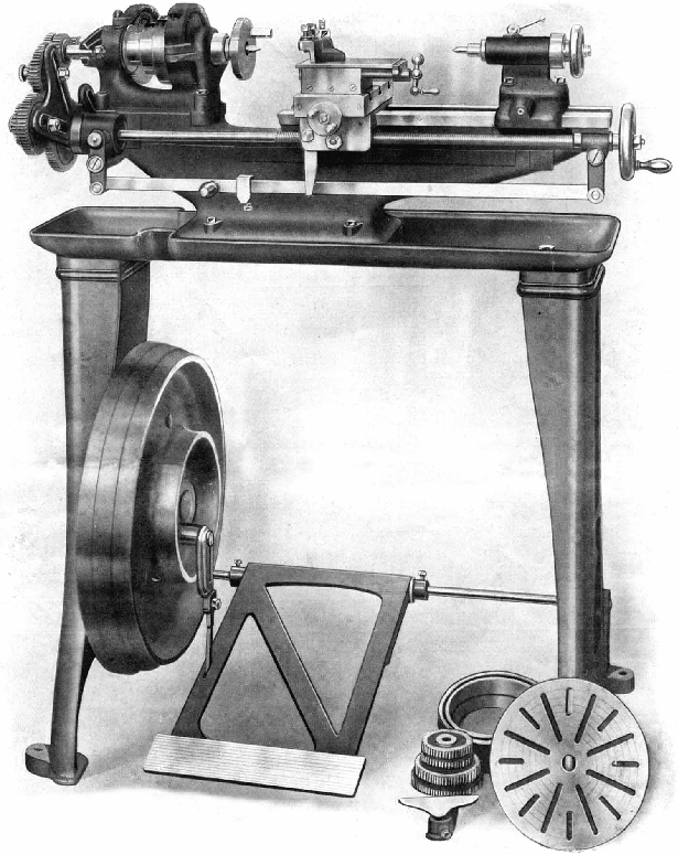
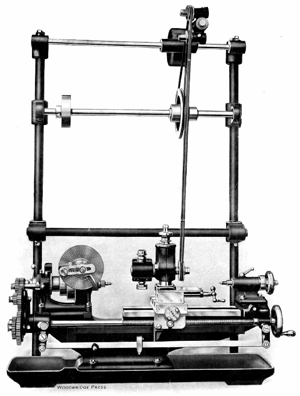
In 1921 Drummond again stiffened and improved their smallest lathe and renamed it the M Type, though this particular version, to be altered again in late 1924, was to have the shortest run of any model, save perhaps the original version produced in 1902 and modified in 1904. The headstock, an entirely new and much improved design, lost the distinctive overhead bracing bar that had previously spanned the bearings and, instead of being allowed to swivel on top of the bed, was positively located against the flat (inside vertical) surface of the front bed shear and held down by four bolts. It was fitted with larger bearings the adjustment of which reverted to an earlier Drummond design where a large ring screwed onto the end of the bearing itself and pulled it into the tapered headstock housing; a proper ball-bearing thrust race was engineered to fit against the inside left-hand end of the spindle. As an aid to heavier rates of metal removal a long-needed, three-step flat-belt pulley replaced the small-diameter round "gut" drive previously used . The spindle nose was again, as in 1912, upgraded and fitted with a 1" x 12 t.p.i. thread backed by a 11/8" register designed to improve the rigidity of screwed attachments. The backgear ratio was changed from 20:60T to 22:66T and engaged by rotating an eccentric shaft instead of sliding into place. Instead of having to reach for a spanner to disengage the 66t bull wheel from its embrace with the belt pulley, a neatly designed "ramp" (that acted as a cam) was machined into a plate on the front of the gear and which could, if all the settings were correct, be persuaded to slide the close-fitting engagement pin out of mesh with the pulley-flange by a push thumb action against a convenient knurled-edge knob. To engage direct drive the backgear was swung away and the knob merely moved slightly in the other direction when a spring on the pin returned it automatically to engage with the pulley. Some years ago writer spent several weeks using one of the lathes and the speed with which backgear could be engaged and disengaged was a delight. The No. 1 Morse taper tailstock was also further increased in strength and the barrel diameter increased from 3/4" to 7/8". The previous rather crude screw-in barrel clamp gave way to a much more elegant and efficient "cotter" or "internally-split" locking device and some machines (but not, surprisingly, all) were given a hollow barrel to solve the problem of how to remove centres and chucks.
Whilst the T-slotted cross slide casting was unchanged, the top slide was all-new: its feed screw was off-set to the side in order to provide a longer and slower-wearing nut and allow the tailstock to come right up to the right-hand face of the cross slide; its base was given an improved (though still hard-to-read) degree-graduated scale on an inserted brass plate; the early-pattern clog-heel toolpost was retained. The cross-slide feed screw handle was modified to have two finger grips and given a zeroing micrometer dial.
Although the changewheels remained unchanged their studs, instead of being fitted with slow-to-remove screw-on knurled-edge finger nuts, were given a new design of (patented) push-in "spring" retainer - a design that was to be used until the end of production. On previous models the changewheel banjo arm had always been retained by a crude through-bolt that ran up against the mounting boss, a design that made it difficult to get enough grip to stop the arm being moved sideways when heavy cuts were taken. This was now supplemented by casting in a curved arm at the back through which passed a stud and nut to ensure that the arm could be firmly locked in place. The flywheel was balanced and ran on a ball race, as did the "pitman" driving link, both helping the operator to maintain a good speed with less effort.

|
|

|
|

|
|
