Drummond "Little Goliath"
EARLY 3 1/2" Drummond Larger Drummonds Round Bed Drummond
Rare early "double-height bed" Model
Drummond Home Page Rare 4" Drummond Flat Bed Admiralty Model M-Type Photo Essay
Early Original 31/2" 1912 31/2" B Type 1921 M Type 1925 M Type
Headstock Comparison Still in Use
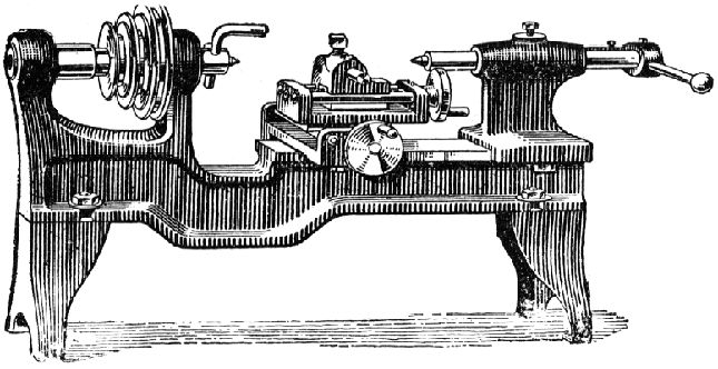
A very rare machine, the smallest Drummond was a plain lathe reduced to the elements of simplicity with the bed and headstock cast as one and a pair of simple feet bolted on at each end. Although produced until the late 1920s the design was decidedly old-fashioned with the aluminium 3-step "gut-drive" headstock pulley carried on a spindle that ran trapped between a conical face on the inside of the front "bearing" and a hardened centre at the back that pushed against an adjustable tube secured by a single square-headed bolt - this system being a variation on a method more commonly found on both inexpensive and better quality lathes from mid to late 1800s. The spindle on early models was threaded internally on its nose with a conical section against which a combined centre and drive dog was drawn. It is possible that later models used a conventional external thread and, if so, would have been much more adaptable to accept special fittings and the carrying of conventional chucks.
Like the 1950s Emco Unimat SL1000 and DB200 the swivelling compound slide rest made use of an inexpensive and easy-to-manufacture twin-bar construction but lacked micrometer dials. Both the carriage assembly and tailstock were bolted to the flat-topped bed by two bolts on their underside, one at the front and another at the rear. A flat brass plate with degree calibrations was trapped between the top slide and cross slide; however, because the plate was not screwed down but only just turned over along its inside edge to locate it, as the top slide was swivelled (or the clamping bolt tightened), the plate moved and the reading changed.
The tailstock made do with just a simple (but very effective) lever-action control for the barrel with the various pivot points provided by ordinary split pins.
It is open to question if Drummond actually made the lathe themselves for the same (or very similar) machines appeared in the 1900 to 1930s catalogues of "hardware" and tool merchants with either just a reference number or an obviously contrived name to identify it.
If you have a "Little Goliath" the writer would be interested to see pictures.

|
|
||
|
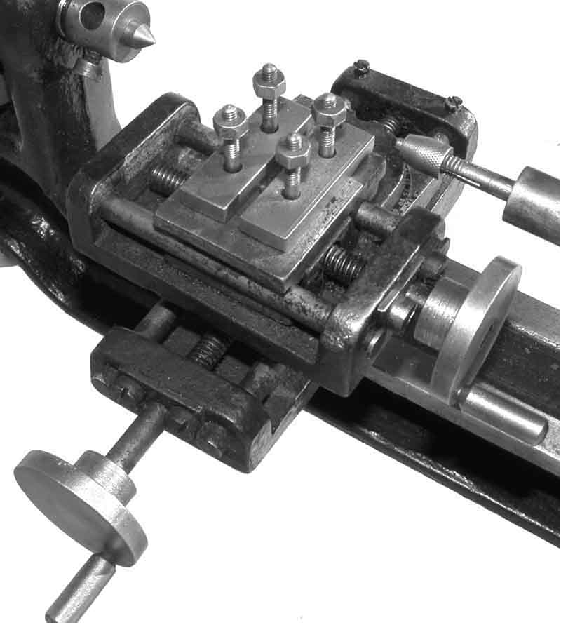
The compound slide used steels bars as "ways". Although made of inexpensive material the bars were a press fit in the casting, a design that called for precise machining. The toolpost, amusingly, was a replica of the type often found on very large English lathes of the period. |
||
|
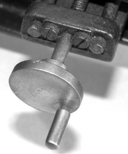
Close examination of the picture will show that the handwheels were retained by a simple pin pressed into a hole drilled through the junction of shaft and hub. |
||
|
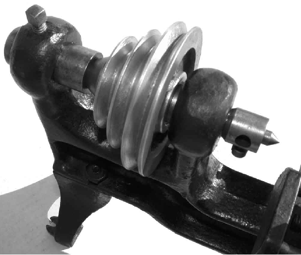
The 3-step "gut-drive" headstock pulley was carried on a spindle that ran trapped between a conical face on the inside of the front "bearing" and a hardened centre at the back that pushed against an adjustable tube secured by a single square-headed bolt. |
||

|
The fitting on the spindle end was a simple screw-in combined centre and drive dog - the bent drive pin being inserted into the hole and secured by a bolt. Drummond "Little Goliath" EARLY 3 1/2" Drummond Larger Drummonds Round Bed Drummond Rare 4" Drummond Flat Bed M Type Early Original 31/2" 1912 31/2" B Type Headstock Comparison Admiralty Model M-Type Photo Essay |
||