|
Continued:
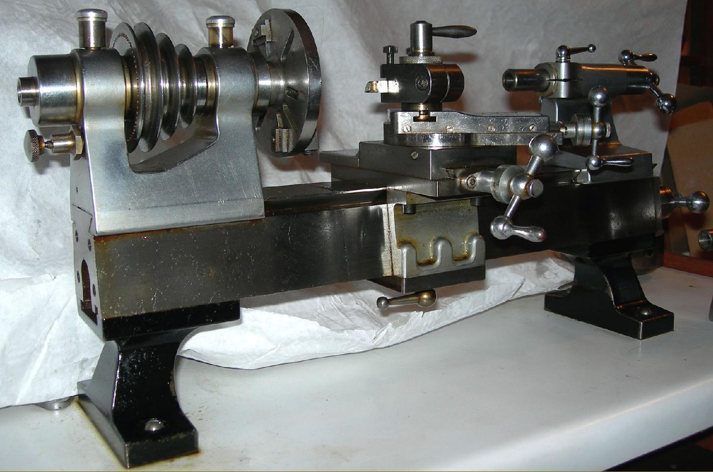
Designated by the company as the Type "GJH" - the appearance of these initials on a surviving general-arrangement drawing is in conflict with previous claims that it was known as the "CY" - the lathe was tiny, but crafted like a larger machine and with noticeably robust headstock and carriage assemblies. The overall length from collet handwheel to the tip of the leadscrew-feed handle was some 25 inches, with the bed accounting for 19 of these. The centre height was 23/8" with 7" available between centres. In a letter from Gordon Hudson he revealed that the bed was machined from a length of case-hardened nickel steel that was ground and then lapped - and the headstock and tailstock cast from close-grained iron. To the writer's eye the iron castings look to have been form milled and hand scraped, in the manner used on Rivett lathes; however, bearing in mind the skill of the builders, it is entirely possible that the fine profile of these units could have been achieved by handwork alone. As a final touch, and to give an exemplary finish, the headstock and tailstock were satin-chrome plated.
Although later used by the Japanese Toyo company in a modified form on their precision ML1 lathe, the bed and saddle design of the GJH was, at the time, possibly unique - and certainly interesting. The top was flat and edged with narrow 45-degree V-shaped ways that guided the tailstock and aligned the headstock. The front and back faces of the bed sloped outwards (forming a trapezoidal shape) and it was on these, and the top surface, that the duplicated front and rear saddles ran. For such a small lathe the resulting contact area, at around 22 square inches, was enormous and with the ways extending to the bottom edge of the bed tremendous support was given to the cutting tool. On the underside of the bed the saddles (formed from castings with bolt-on top and bottom plates made to a dead fit), appears to have been located against an inner vertical surface by one face of the bronze carriage feedscrew nut. The carriage was propelled along the bed by a graduated handwheel at the tailstock end that drove a feedscrew running centrally down the bed and gripped by a nut set immediately below the toolpost. Because of this construction, and doubtless very careful assembly and fitting, the carriage moved with the slightest touch on the handle, yet had absolutely no play.
Running in traditional, adjustable, hardened steel plain bearings - conical at the front with a steep taper and at the rear with a parallel bore but sitting in a tapered housing - the hardened, ground and lapped headstock spindle carried a threaded nose and accepted 8 mm draw-in collets. Simple wick-feed oilers provided lubrication. The 3-step pulley took a round belt and was arranged with its largest diameter to the left with the outer flange carrying a ring of 60 indexing holes; these were engaged by a particularly strong pin that passed through the left hand wall of the headstock.
Conventional in appearance, though beautifully finished in polished steel, the cross and top slides were broad and with sufficient gib strip adjustment screws to ensure that the setting would could be absolutely precise over the slide's whole length. The cross slide had a travel of 2 inches, the top slide 1.5 inches with their feed screws made from hardened nickel steel. The 0.001" graduated micrometer collars were also hardened and could be locked by small knurled-edged finger screws that ran through the centre of the handles. By causing the dial to travel axially (and not tending to tilt it over, or move it sideways, as conventional locking screw are prone to do), this arrangement avoiding any alteration in the setting. Even the balanced ball handles were special and, reflecting Rivett practice, were retained not by a crude taper pin but by screws that passed neatly down the shank of each ball-ended shaft. A "Norman Patent" toolpost was used, (identical in concept to that used for many years on the popular Drummond M-Type) that was able to be both quickly altered in height and swivelled around its mounting boss - but with the added sophistication that the whole unit was self contained and could be instantly released and slid out of its T-slot holder. It's possible that, like many precision lathes two tailstocks would have been provided, each with 1.5 inches of barrel travel: one took a morse taper centre the other being adapted for 8 mm (draw-in) collets. Both tailstocks were designed so that their centres could meet that of the headstock, yet still leave sufficient room to use a range of slide rest movements.
As an example of what the lathe could produce a sample was retained with it of a minute bush: just 0.025" long with a diameter of 0.008" and a 0.004" bore it requires a powerful magnifying glass to appreciate..
|
|