Home      Machine Tool Archive      Machine Tools For Sale & Wanted
E-MAIL   Tony@lathes.co.uk

G. BOLEY LATHES
Accessories   Boxed Lathe Sets   Accessory Photographs   Boley Capstan Lathes
   Late Model 4L   Boley Milling Machines   Stands & Drives   Special Hand-capstan Unit
Watchmakers' Lathes Headstock Bearings

G.Boley were established in Germany in 1870 and went on to make a world-renowned range of precision machinery and equipment of all kinds - from miniature watchmakers' to medium-sized production lathes, various kings of milling machines and a vast range of watch and clock-making tools and accessories.
Some confusion has arisen in recent years about the connection between "G.Boley", "Boley & Leinen" and "Leinen". Whilst G.Boley were nothing to do with the other two, Leinen and Boley & Leinen were the same company and used two names as marketing tools. In general their smaller machines were "Boley & Leinen" and the larger more sophisticated ones "Leinen".
A contact writes:
The basic story, regarding the two Esslingen firms, I got either from Gunther Leinen, the grandson of the founder or from Fritz Carl Mahr, who was a good friend of Gunther's and the principal owner of the big measuring instrument firm of Carl Mahr.
I also knew the son (Gunther's father) who was owner and manager of the firm at the end of the war - when, as an American Serviceman, I had my first contact with Boley and Leinen and with the firm of G.Boley. In any event, I was told that the manner by which Boley & Leinen acquired the Boley part of the name was a matter of acute embarrassment to the Leinen family. The founder of the firm, Gunther's grandfather, had been employed by G. Boley, and left them, initially, to manufacture the bench vise of his design. This vise was always marked "Leinen" even though it was always manufactured by Boley & Leinen.  G. Boley also made an exact copy of this very popular item. My understanding is that Leinen was quite successful with the vise and decided to go into the watchmaker's lathe business; in direct competition with G. Boley; an already well-established name. Supposedly he search the town directory and located a not particularly well-off widow with the family name of Boley and persuaded her to become a "partner" in his firm. His firm thus became "Boley & Leinen".

The works of G.Boley and Company in 1924

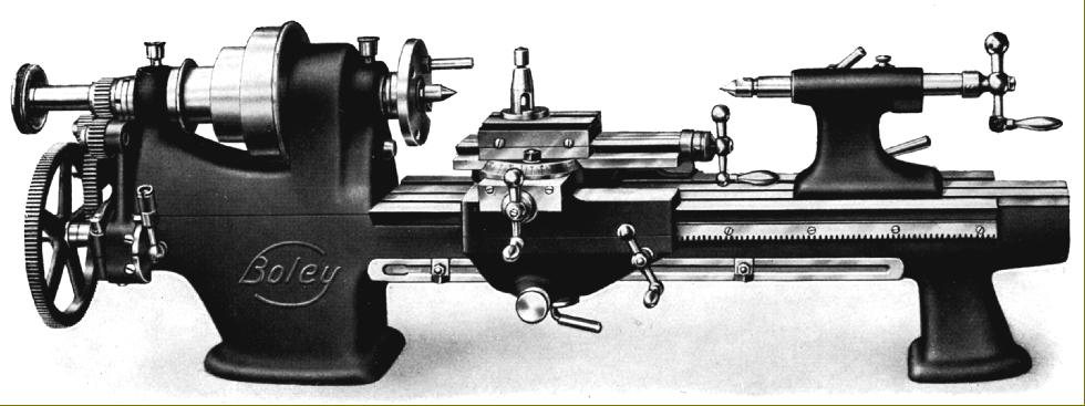
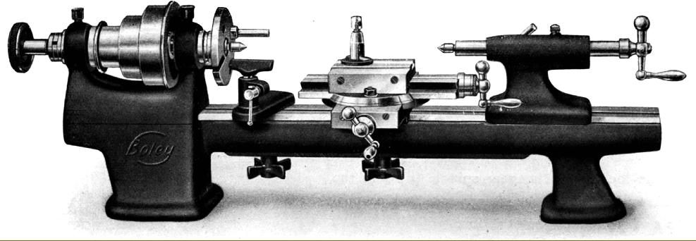
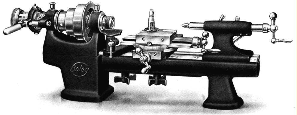
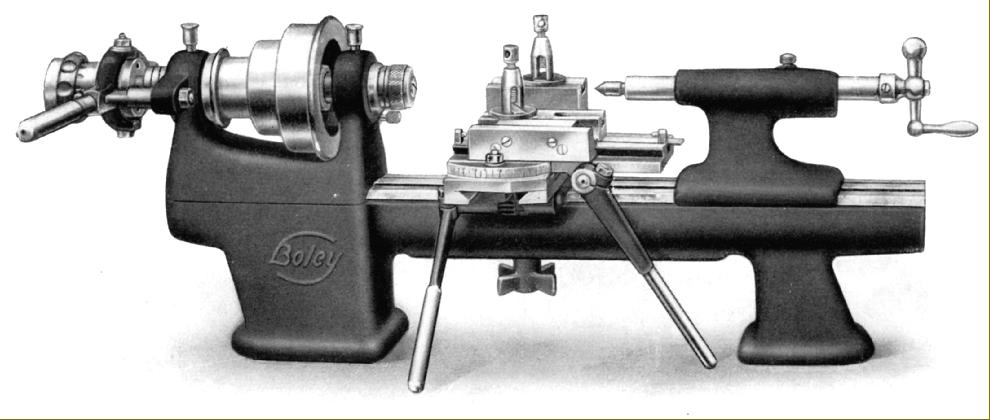
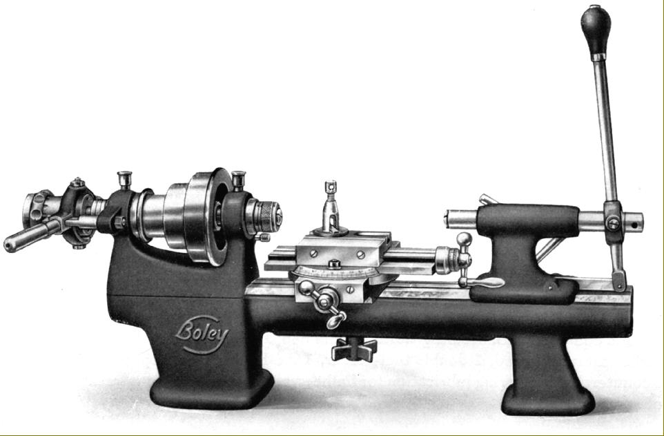
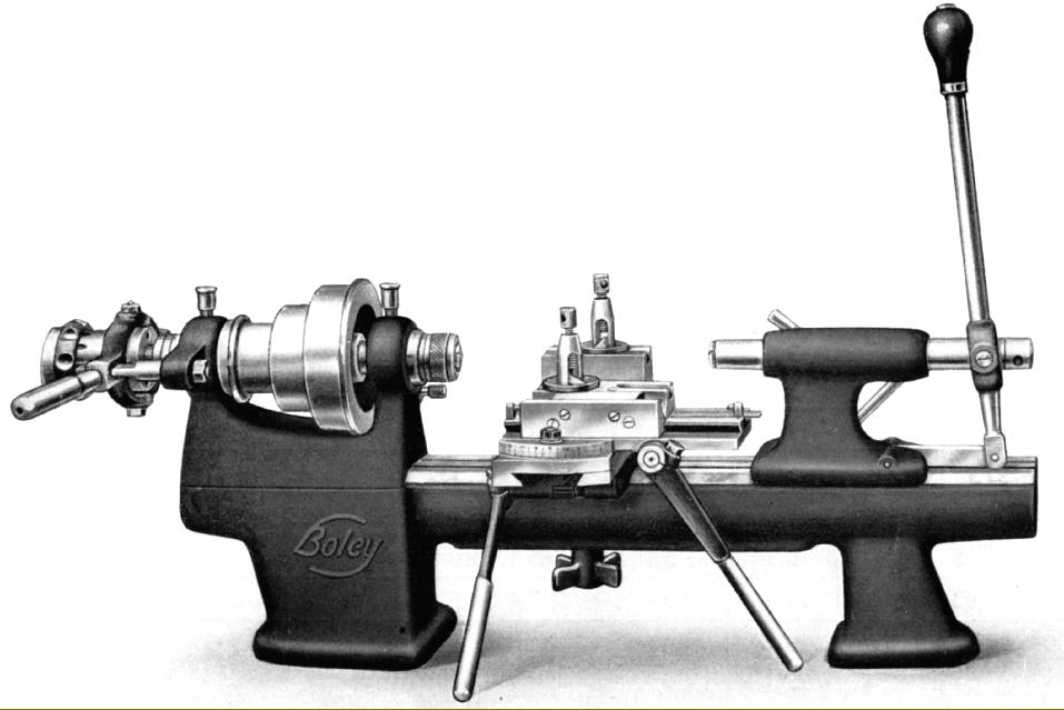
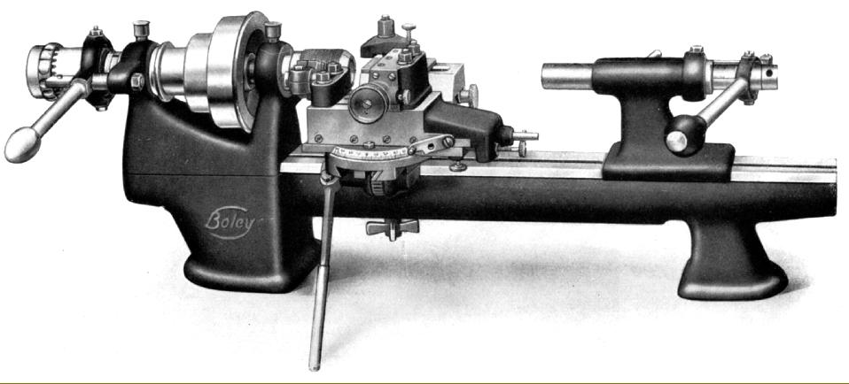
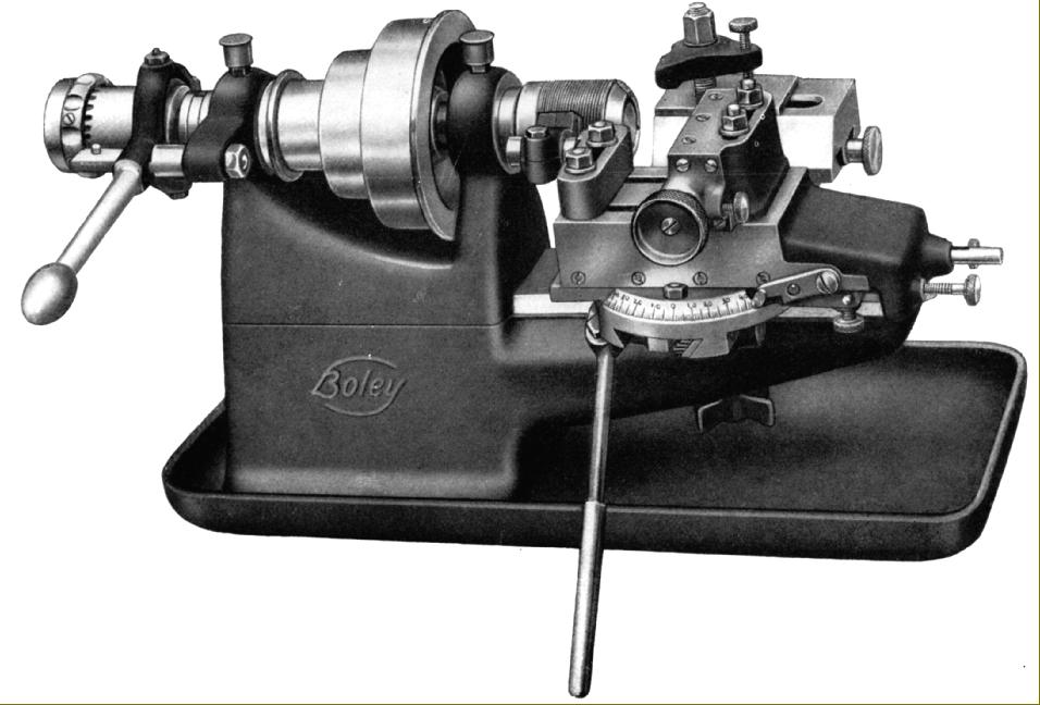
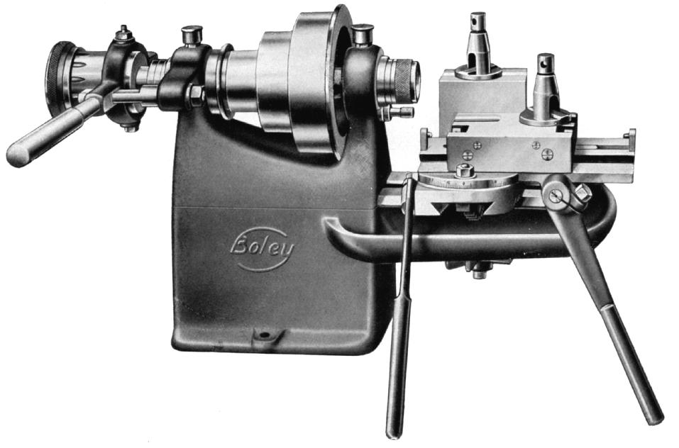
One of  G.Boley's most popular and enduring models was the Series 3 and 4 - both very similar in construction but with the No. 3 lathe being of 90 mm (3.5") centre height and the No. 4  120 mm (4.7"). Illustrated below (with a photographic essay here of a later, more highly-developed model), these were enormously heavy, cleverly designed, beautifully made and elegant machine tools produced in a wide variety of models and with suffixes such as L, C, L, H, R, CR, BJ, HL, HM, etc., the designation reflecting a precise specification and level of standard equipment. Whilst many were produced as plain-turning precision lathes, or set up with lever-action collet closers, capstan heads and cut-off slides for mass production work on small, close-tolerance components used in the watch, clock and instrument industries, large numbers were also manufactured as backgeared and screwcutting models for use in toolrooms and repair shops. On the latter type the leadscrew ran in a fully-shielded housing beneath the bed whilst the twin "aprons" (they reached down both in front of and behind the saddle to form a particularly rigid housing) were joined together by a casting that supported the clasp nut in a perfect position directly beneath the centre line of the carriage and almost underneath the toolpost.
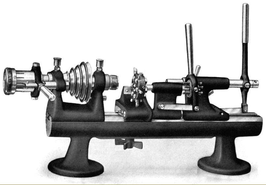
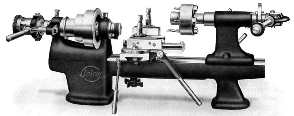
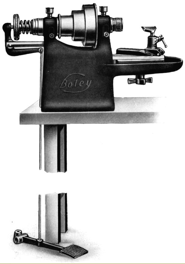
The backgear and its engagement system (when fitted), was neatly enclosed within the headstock casting directly behind the chuck and was a masterpiece of compact engineering, if a little awkward to engage on early versions--and a complete mystery if you don't know how. The secret lies in a small pressed-steel lever on the face of the headstock beneath the chuck (used to engage and disengage the gears) and a difficult-to-locate small screw marked (in very small lettering) "AUS" and "EIN" (in and out) on the side step of the middle pulley. If the screw is turned through 180 degrees, whilst simultaneous oscillating the pulley, a slight "clunk" will be heard as a small spring-loaded pin engages (or disengages) the pulley from the inner bronze backgear. With the pin out of engagement the pulley is free to turn on the spindle (together with its bronze gear) and so engage the backgear assembly to give slow speeds. The pushing force for the pulley-to-gear engagement pin was provided by a powerful spring, contained in a housing bored down through the depth of the largest diameter pulley. The tapping was capped by a large slotted screw that should be removed only if necessary (and be sure to contain the bits as the plug screw comes out). The saddle drive was fitted with an automatic, pre-set disengage to both left and right travel - a most useful facility when taking a long, fine-finishing cut. On some versions of this lathe the headstock pulley ran in its own bearings (concentric to the main spindle bearings) and drove the spindle though a peg - thus relieving the spindle of any loads from the driving belt.  The "tumble-reverse" was unusual in that the whole of the banjo arm carrying the changewheels was swung through an arc to pick up the respective drive gear. A knurled-finished handle below the left-hand headstock bearing operated the mechanism. The lathe was available in several other short-bed versions - the H, a simple repetition lathe, the PA for polishing, PS for finishing and the G for finishing and re-cutting threads. Several different stands were available, all of simple design with cast-iron legs and either wooden or metal tops. Models from the mid 1930s were offered with the option of a neat under-drive cast-iron stand with the flat-belt final drive coming from a V-belt countershaft unit built into the lower part of the headstock-end leg (illustrated below).
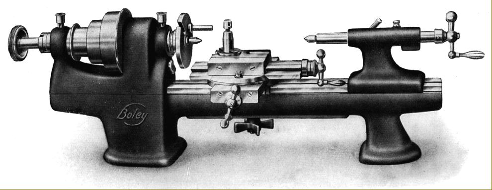
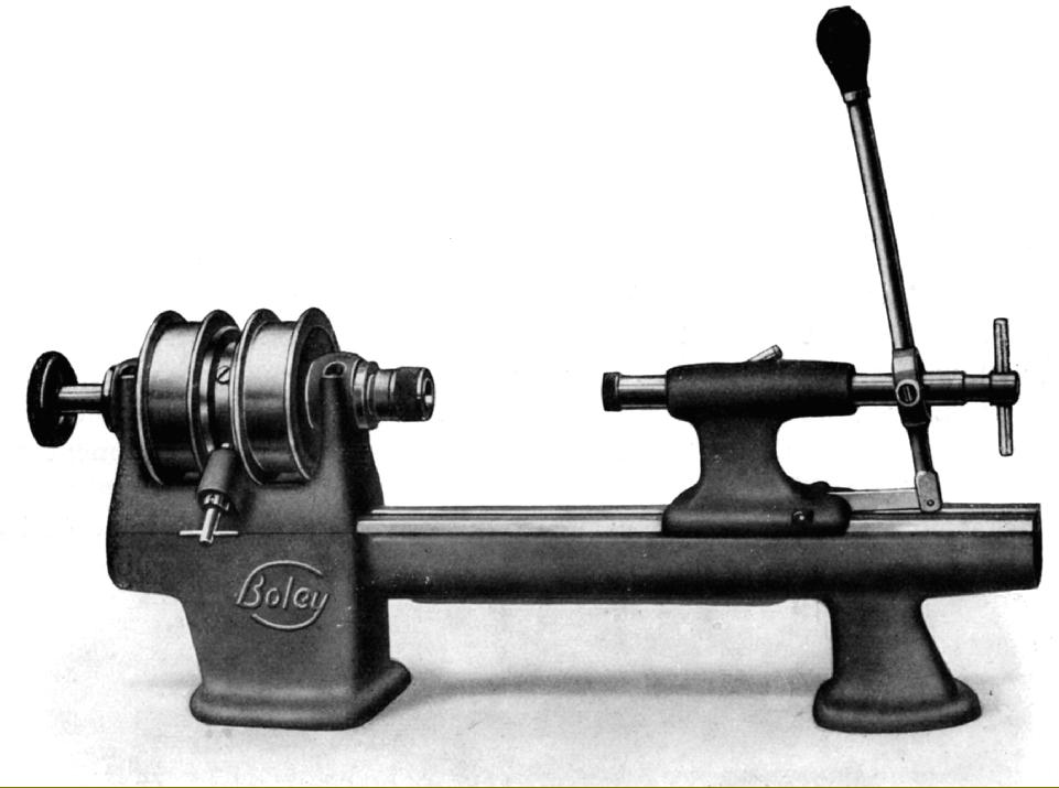
The plain turning precision lathes used a very much simpler form of bed than the screwcutting models, although parts of the compound slide and tailstock - as well as a number of accessories - were common to all types and could be easily interchanged.
It is likely that some G.Boley models, both precision pain turning and screwcutting, were re-badged (or cloned) as "Swisten" for distribution in the UK.

Boley Model 3L/4L precision screwcutting and backgeared lathe as first manufactured in the 1920s. Tumble reverse was operated by rocking the whole of the changewheel quadrant arm. In later years the 4L was made even more rugged and useful by modifying the bed, extending the saddle wings forwards and mounting the lathe on a heavy stand with an underdrive countershaft. Pictures below. The Boley 4L formed the basis for the post-war English Smart & Brown Model M )

Plain-turning Boley 3C (90 mm centre height) and 4C (120 mm centre height) with draw-tube collet closer and screw-feed compound slide rest. Theses were the simplest of the Boley 3 & 4 series and supplied for either bench mounting, or on choice of several different stands.

Boley lathe No. 3R and 4R. Almost identical to the No. 3 and No. 4 but fitted with a hardened-steel and phosphor-bronze back-gear assembly to give a range of slow speeds. 

Boley 2HN lathe with lever-operated collet closer and an unusual 6-position turret head on the hand-like tool rest. More details here

Plain-turning Boley 3BJ lathe with lever-action collet closer and a standard compound slide rest

Boley 3H with all lever-action controls: collet closer slide rests and a tailstock with an indexing multi-tool holder

Boley 3HK--similar to the 3H but with an ordinary screw-feed tailstock

Boley 3HL: lever-action collet closer and collet-holding tailstock with a screw-feed compound slide rest

Boley 3HM: an all lever-feed model for production work

Boley 4PP thread-chasing lathe

Boley 4PQ precision finishing lathe with thread-chasing attachment

Boley PS lathe for short, collet-held repetition work

Boley Model G tapping lathe. The two headstock pulleys were driven by belts running in opposite directions.  A dog clutch, set between the pulleys, was arranged to flick from one drive to the other, so reversing the tap at high speed. Many users used ingenious adaptations to this design including automatic operation of the clutch controlled by mercury switches.

Boley PA polishing lathe--though its actual use was for hand-turning or the finishing of small parts - the foot-operated collet closer allowing the operator to rack up a good bonus if he had taken tap-dancing lessons.