 |
|
|
|
|
|
|
|
|
|
|
|
|
|
|
|
|
|
|
|
|
|
|
|
|
|
|
|
|
|
|
|
|
|
|
|
|
|
|
|
|
|
|
|
|
|
|
|
|
|
|
|
|
|
|
|
|
|
|
|
|
|
|
|
|
|
|
|
|
|
|
|
|
|
|
|
|
|
|
|
|
|
|
|
|
|
|
|
|
|
|
|
|
|
|
|
|
|
|
|
|
|
|
|
|
|
|
|
|
|
|
|
|
Home Machine Tool Archive Machine Tools For Sale & Wanted
E-MAIL Tony@lathes.co.uk
G. BOLEY Late-model 4L Lathe
Boley Home Accessories Boxed Lathe Sets Accessory Photographs
Boley Capstan Lathes Late Model 4L Boley Milling Machines
Stands & Drives Special Hand-capstan Unit Watchmakers' Lathes Headstock Bearings
A reproduction of superb 86-page Boley lathe & watchmakers' tools catalogue is available:
e-mail for details
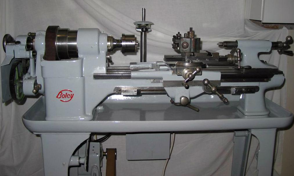
The late-model 4L , manufactured from the mid 1930s into the 1940s , showed numerous improvements over the first version with the top slide given greater travel and the tailstock provided with a longer and more robust casting. However, the most significant alterations were to the bed and saddle with the latter being thicker over its centre section and with very long arms added to its left-hand side. The was bed altered so that the ways ran on past the front and back of the headstock so proving greatly improved support for the cutting tool as it neared the spindle nose. That part of the bed abutting the headstock was braced by the addition of a large triangulated section on the underside, headstock given a more robust spindle, running in larger diameter bearing, and the backgears increased in size to cope with heavier work. The 3-step pulley was reversed, to bring the largest diameter to the left, and the arrangement for engaging backgear - previously rather fiddly - redesigned for simpler and more certain operation. The 4L illustrated below is fitted to an underdrive stand, the cost of which (if other Boley lists are a safe guide), would have nearly doubled the price of the basic machine.
|
|
|
|
|
|
|
|
|
 |
|
|
|
|
|
|
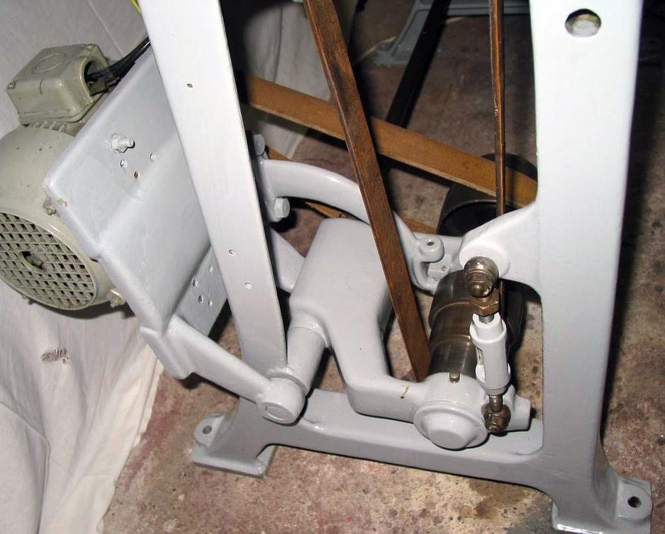
Probably built in the mid 1930s this Boley 4L is of the under-drive type with a neat, self-contained and easily-adjusted countershaft system
|
|
|
|
|
|
|
|
 |
|
|
|
|
|
|
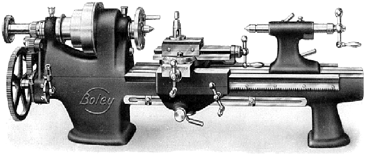
Early "short-saddle" 4L for comparison
|
|
|
|
|
|
|
|
 |
|
|
|
|
|
|
Although mechanically unchanged on late models, the "swinging bracket" tumble reverse system was at last provided with some perfunctory safety guarding.
|
|
|
|
|
|
|
|
 |
|
|
|
|
|
 |
|
|
|
|
|
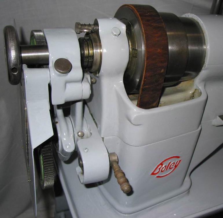
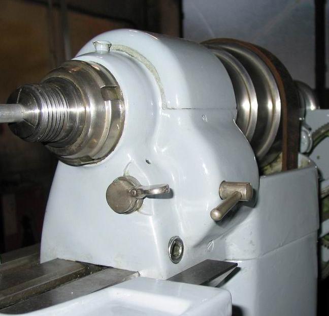
A powerful lock was provided to hold the spindle - a useful fitting so often neglected by lathe manufacturers
|
|
|
|
|
|
|
|
 |
|
|
|
|
|
|
On the front face of the headstock the backgear engagement lever - at the back a lever to clamp the setting
|
|
|
|
|
|
|
|
 |
|
|
|
|
|
|
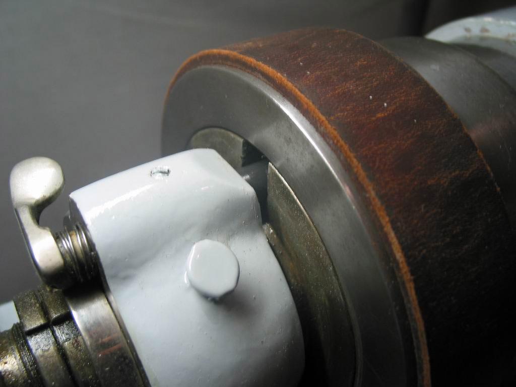
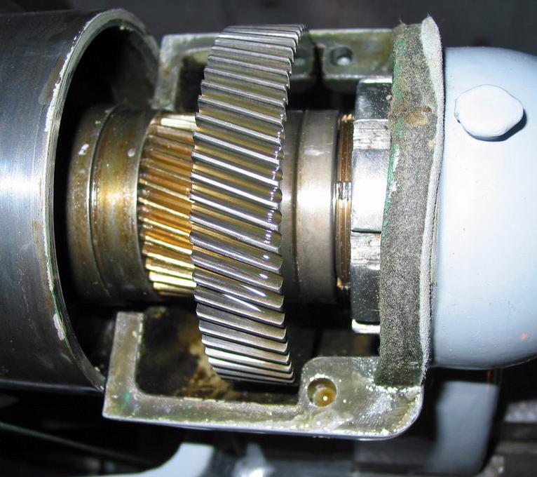
Helical backgear assembly. Engaged and disengaged by a single lever the gears could be locked in place by a clamp lever at the back of the headstock. However, in normal use, the gears remained in position without this precaution
|
|
|
|
|
|
|
 |
|
|
|
|
|
|
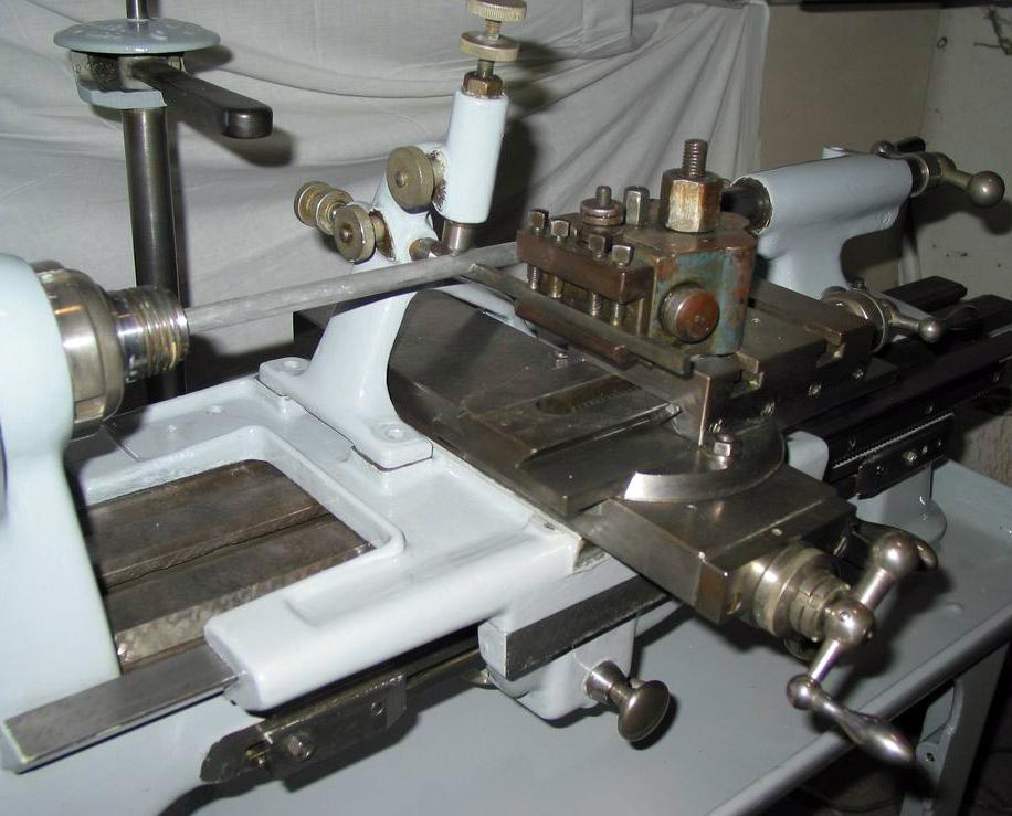
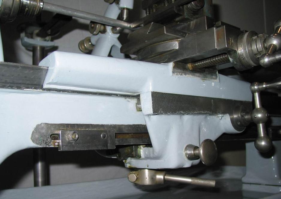
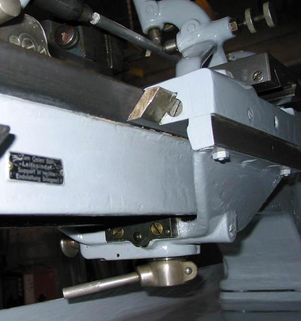
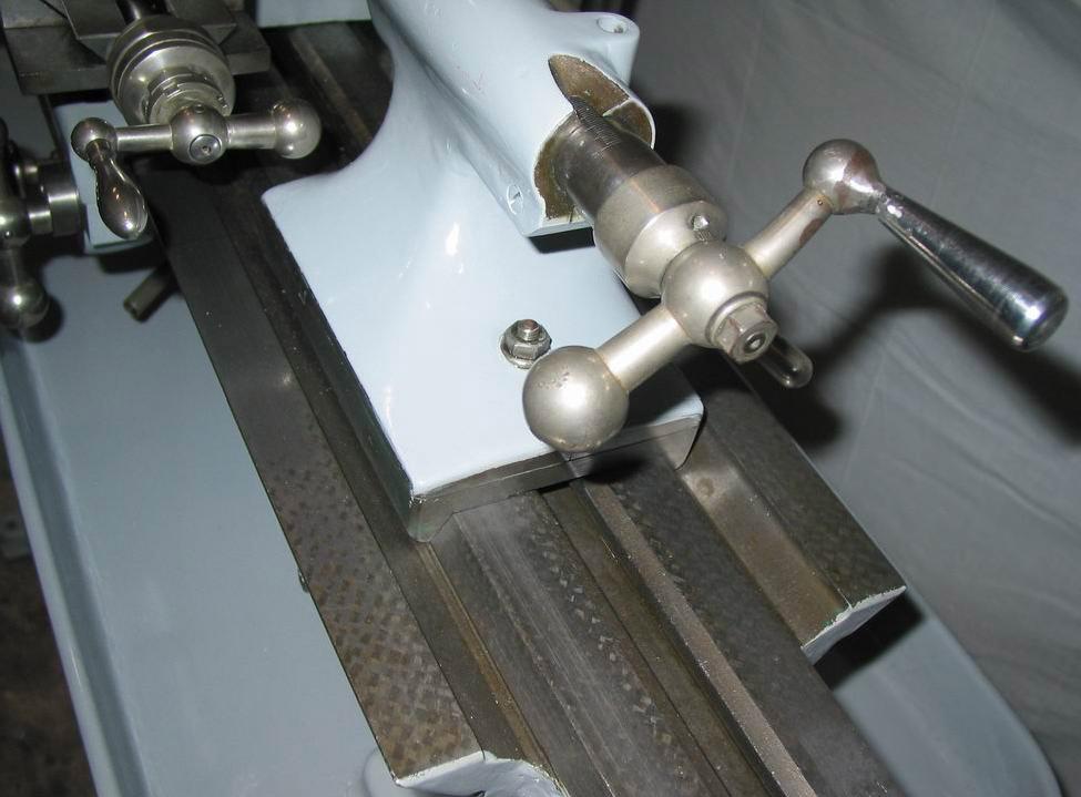
A view showing the enormously extended wings of the late-model 4L saddle. Note the early design of quick-set toolpost
|
|
|
|
|
|
|
 |
|
|
|
|
|
|
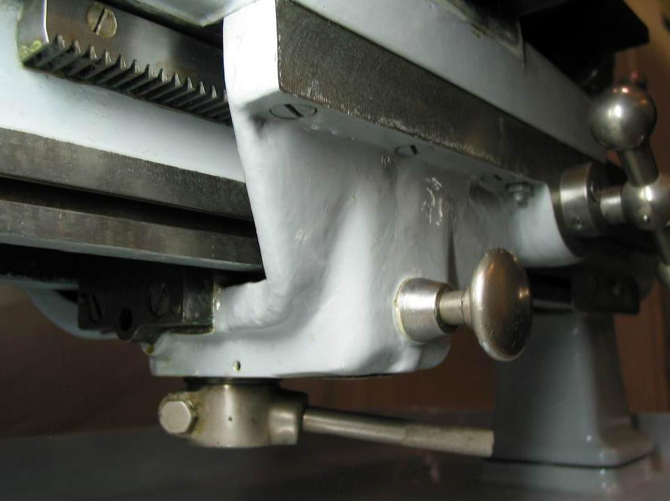
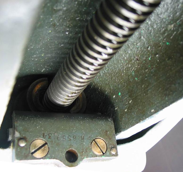
The carriage feed could be disengaged by an adjustable wedge carried in a T-slot machined into the lower front edge of the bed.
|
|
|
|
|
|
|
|
 |
|
|
|
|
|
|
A view from the rear of the heavy casting used to join front and rear aprons and carry the leadscrew clasp nuts
|
|
|
|
|
|
|
|
 |
|
|
|
|
|
|
Leadscrew clasp-nut engagement lever and button-trip control for quick release by hand.
|
|
|
|
|
|
|
|
 |
|
|
|
|
|
|
|
|
|
|
|
 |
|
|
|
|
|
|
No micrometer dial on the tailstock barrel--but the design followed long-established precision lathe practice by locating the nut inside the barrel, so allowing it to be fully supported no matter how far in or out it was extended.
|
|
|
|
|
|
|
|
 |
|
|
|
|
|
|
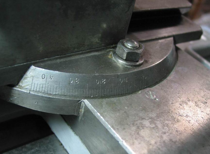
Graduations on the top-slide base extended to 45º each side of zero
|
|
|
|
|
|
|
|
 |
|
|
|
|
|
|
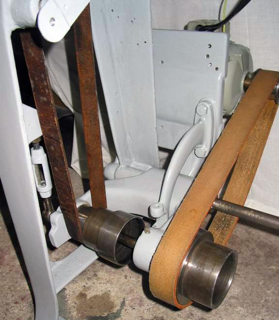
Neat turn-buckle adjustment to set the final-drive belt tension
|
|
|
|
|
|
|
|
 |
|
|
|
|
|
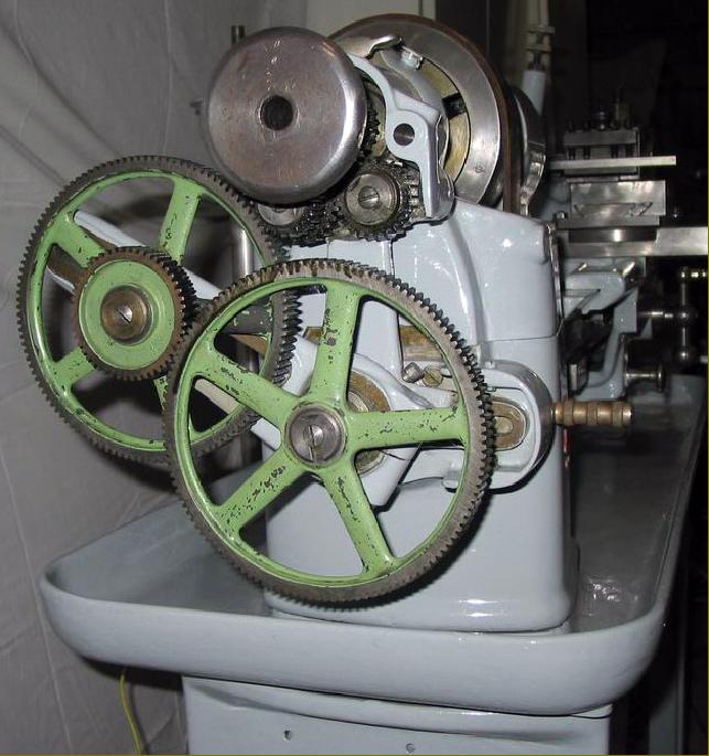
Substantially constructed the countershaft provided 2 drive speeds from the motor and three to the headstock. Combined with back gear the 12 speeds produced spanned around 40 to 1500 r.p.m.
|
|
|
|
|
|
|
|
|
|