Drummond

Home    Machine Tool Archive    Machine Tools for Sale & Wanted    E-MAIL:Tony@lathes.co.uk

Drummond B-Type, M-Type &  Myford M-Type Lathes
Page 1 of 2
Click HERE for more information on Page 2
Copies of the Maker's Literature, Screwcutting Charts, etc. are available     Headstock Comparison 
EARLY 31/2" Drummond
    Larger Drummonds   Round Bed Drummond  Rare 4" Drummond Flat Bed
1925 M Type  Early Original 31/2"  1912 31/2" B Type  1921 M Type   Admiralty Model  Little Goliath
  M-Type Photo Essay    Rare early "double-height bed" Model   Still in Use
Literature for Drummond lathes, gear shapers and other machine tools is available. Email for details

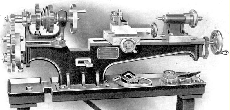
Introduced in 1902 the Drummond flat-bed 3.5" x 16" (and rare 20-inch version) was, in its various guises, to continue in production for almost half a century with the final model, the M-type (introduced in 1921) being assembled (by Myford, from spares), as late as the 1952. Although the early flat-bed lathes are often all referred to as the "B Type" strictly speaking that designation did not apply until the appearance of a much-modified lathe in 1912 - and after the introduction of the Round Bed, in 1908, a lathe Drummond called the "A Type". However, the maker's contemporary catalogue description, "31/2-inch Centre Back Geared, Self-acting Sliding, Boring, and Screwcutting Lathe" whilst accurate, is a little long for handy use - so for the purpose of easy reference to the very first flat-bed lathes we might call them "Mk. 1 Pre B-Type Flat Beds".
In sacrificing some rigidity in favour of stylistic adornment the lathe followed late 19th century practice (note the shape of the bed and the graceful sweep of the headstock casting) but the design was sound and the features introduced during the first few years of production - a compound slide rest, adjustable headstock bearings, dog clutch on the leadscrew, backgear, set-over tailstock and swing headstock - were guaranteed to appeal to the market. A wide range of accessories (milling slides, grinding attachments, wood-turning rests, overhead-drive system, etc.), was also made available. The spindle was driven by a round leather "rope" (sometimes called a "gut-drive") that passed over the chip tray in the two highest speeds, but though slots in its edge on the lowest, to a treadle-operated flywheel mounted on the left-hand leg of the cast-iron stand; the latter seem to have had legs built in at least three different heights, according to the examples that have passed through the writer's hands over the years.
Introduced in 1908 the Round-bed Drummond was intended to sell at the "bottom-end" of the market and had, by the end of its production in 1939, proved to be a very popular and successful machine, especially amongst amateur turners. However, this was not the cheapest Drummond ever offered, that honour belongs to the "Little Goliath" - which was both the least expensive and smallest - with its compound slide rest ways constructed from pairs of steel bar, a design also used by the Austrian Emco company during the early 1950s for their mass-production SL1000/DB200. Several larger lathes were also made, including the interesting  Drummond-Barreto, but the range of heavy lathes was very restricted when compared with the wide variety offered by contemporary firms such as Lang, Butler, Swift, Smith & Coventry, Dean, Smith & Grace, Binns & Berry, Willson and Denham. Fortunately, despite their initially limited product range, Drummond managed to sell many examples to the British armed services and company records have survived that make it possible to identify even which particular warship a Drummond lathe was allocated to. A surprising number of these older lathes are still about in original condition (even with their treadle gear) and make both a useful and interesting addition to any enthusiast's workshop.
In October 1953 the Drummond Company was bought by Asquiths, another well-known English machine-tool concern, who wanted to expand their involvement in multi-tool, copying lathes and gear-hobbing machinery. Staveley Industries, who had used capital acquired during the 1950s as compensation for the post WW2 nationalisation program to buy a range of British machine-tool companies, acquired control of Asquiths in 1966. Even though the original Drummond-designed multi-tool lathes, the
Maximatic and Maxirapid, together with a gear shaper, the Maxicut, were made until about 1970 the writing was on the wall and, by 1981, Staveley (whose technical knowledge and marketing abilities were regarded with derision throughout the industry) had asset stripped many of its firms, closed their factories and sold off the land.
Although outside the remit of this article, the range of Drummond's post WW2 industrial machines consisted of various models the origins of which can be traced back to the introduction in the mid 1930s of an "Electraulic" broaching machine the Model WA (discontinued in 1948) and the Maxicut No. 00, Maxicut No. 0, Maxicut (no number), Maxicut No. 1 and Maxicut No. 2 production lathes. These original machines continued in various forms, with gradual deletions to the  range until the last of the libe, a Maxicut No. 1 Type Y, was made in 1951.
A more complex multi-tool lathe, the
Maximatic, and its smaller companion, the Maximinor, were introduced in 1946 and continued in production until 1964. A copy-turning lathe, the Maxicut Electronic (with electronic controls) was first shown in 1955, and made until 1961 whilst another multi-tool lathe, the Maximajor, had a three year run from 1955 to 1958. The last lathes to be developed were the Maxirapid multi-tool and Maxipilot copying lathes: these were manufactured from 1958 until at least 1970 in the case of the former, and 1964 in the case of the latter - the year the Hoblique hobbing machine was introduced.  Besides lathes Drummonds also produced a very popular range of gear shapers the 2A, 2B, 2C, 3A and 4A - the Maxicut 2A being introduced in 1946 and built alongside the larger 4A (introduced in 1949) until after 1970. Another type of gear shaper, the FD, was also produced in several models and ran from 1946 to 1952. The Drummond gear shapers are still produced today, in an improved form, and a full back-up and spares service is available for older models.
Continued below:

1908 Model with the first compound slide rest. Originally fitted with full-circle handwheels it quickly reverted to the more traditional cranked type shown in the picture below.

CLICK HERE  for more pictures and information about the ORIGINAL MODEL

Drummond B Type circa 1912--1921. In reality, a completely new model incorporating much fresh thinking about how a small lathe should be constructed. For a series of detailed photographs of this type, click HERE

Continued:
For the first ten years of production Drummond retained the basic structure of their original small flat-bed lathe largely unchanged; however, every twelve months or so, some small but significant changes were made to the specification and these alterations can be used to date early machines with reasonable accuracy. A more detailed look at the first lathes, their development and alterations made over the years, can be found HERE.
Although Drummond may have considered a developed version of the early lathe - one meeting that criteria has been found in Australia - in 1912 Drummond introduced what was, in reality, a completely new model  that bore the official title "B Type". The bed was made much heavier and stiffer, with the saddle thrust taken on a vertical surface on the inside of the front way, a bar cast between the headstock bearings above the spindle pulley to improve rigidity (and reduce tool chatter) and the spindle-thread size was increased in size from 3/4" to 1". The leadscrew was moved from the middle to the front of the bed and the dog clutch fitted with a useful pre-set automatic throw-out facility. The changewheel arm (banjo) became V-shaped and allowed wider spacing of the changewheels - and hence the opportunity to use larger gears and make the carriage travel more slowly on its finest feed. Interestingly, the same original error - of trying to employ a cheap, single-slot changewheel arm - was made by South Bend on the introduction of their inexpensive Model 5 lathe in late 1931). As on all small Drummond lathes (including the much later Myford M-Type) the changewheels were 14 DP with a 14.5 degrees pressure angle; today, unfortunately, the standard pressure angle is 20 degrees so "off-the-shelf" gears will not match satisfactorily; if a new gears are required they have to be specially made. To connect the gears in pairs for a compound train each gear carried a pin and a pin hole; the pins are seated in tapered holes and, if driven out the wrong way, will fracture the gear. To go with the rest of the improved machine the tailstock was completely redesigned and fitted with a guidance similar to that of the saddle - but the solid barrel was retained. The original style of round-rope was left in place to complete a few more years' service, but the stand was entirely different and made much heavier and stiffer - however the original holes, that allowed belt passage on the lowest speed of the earlier models, were still retained.
In 1915 a thick gib 'block' was fitted at the front of the saddle in place of the original gib strip at the rear - which meant that tool thrust was now taken against a solid surface - not a strip of metal supported at three places by pointed screws - and the rigidity of the saddle-to-bed fitting enormously improved.  A larger cross slide was also incorporated that had, at least in some cases, a micrometer dial fitted to its feed screw--though whether this was a standard fitting, or an accessory, is not clear. The true centre height was also increased to 3
5/8"
In 1916 the Mk. 1 "B.S. Type" was introduced for Admiralty use with a range of modifications to ease the difficulties encountered when turning in a rough sea. It was closely based on the standard "B Type" machine but fitted with a power-feed apron with both longitudinal and cross feeds taken from a shaft fitted below the leadscrew and geared to its left-hand end. A saddle traverse by hand-wheel to a rack and pinion was also included (but not the contemporary standard lathe) and a tumble-reverse mechanism fitted to the changewheel drive. This was neatly fitted to the slotted bracket on the headstock front that normally carried a stud to mount the extra changewheel required for left-hand screwcutting; when the tumble reverse unit became available on the B.S. it also entered the accessory lists for the standard machine. "B Type" lathe beds of the era can be identified by the "pads" cast onto the front face of the bed to accept the power cross feed layshaft assembly. On the Mk. 1 BS the power-feed selector arm worked across the front of the apron whilst on much more common Mk. 2 it was positioned to hang downwards and indent into the underside face. There is no evidence that the BS was made available for civilian use, it being entirely absent from Drummond catalogues of the time.
Continued below:

Getting stronger: the penultimate version of Drummond's small lathe the "new-for-1921" M Type. This version lasted only 4 years before being replaced with an improved model. More pictures of this variant here.

Continued: Drummond 1921
In 1921 Drummond again stiffened and improved their smallest lathe and renamed it the M Type, though this particular version, to be altered again in 1925, was to have the shortest run of any model (save perhaps the original model produced in 1902 and first modified in 1904). The headstock, an entirely new and much improved design, lost the distinctive overhead bracing bar that had previously spanned the bearings and, instead of being allowed to swivel on top of the bed, was positively located against the flat (inside vertical) surface of the front bed shear and held down by four bolts. It was fitted with larger bearings the adjustment of which reverted to an earlier Drummond design where a large ring screwed onto the end of the bearing itself and pulled it into the tapered headstock housing; a proper ball-bearing thrust race was engineered to fit against the inside left-hand end of the spindle. As an aid to heavier rates of metal removal a long-needed, three-step flat-belt pulley replaced the small-diameter round "gut" drive previously used . The spindle nose was again, as in 1912, upgraded and fitted with a 1" x 12 t.p.i. thread backed by a 1
1/8" register designed to improve the rigidity of screwed attachments. The backgear ratio was changed from 20:60T to 22:66T and engaged by rotating an eccentric shaft instead of sliding into place. Instead of having to reach for a spanner to disengage the 66t bull wheel from its embrace with the belt pulley, a cleverly designed "ramp" (that acted as a cam) was machined into a plate on the front of the gear. If everything was adjusted to slide easily, a swift push by a gnarled thumb against a knurled-edge knob was sufficient to persuaded the close-fitting engagement pin out of mesh with the pulley-flange. To engage direct drive the backgear was swung away and the knob merely moved slightly in the other direction - when a spring on the pin returned it automatically to engage with the pulley. The writer spent some time using one of the lathes and the speed with which backgear could be engaged and disengaged was a delight. The No. 1 Morse taper tailstock was also further increased in strength and the barrel diameter increased from 3/4" to 7/8". The previous rather crude screw-in barrel clamp gave way to a much more elegant and efficient "cotter" or "internally-split" locking device and some machines (but not, surprisingly, all) were given a hollow barrel to solve the problem of how to remove centres and chucks.
Whilst the T-slotted cross slide casting was unchanged, the top slide was all-new: its feed screw was off-set to the side in order to provide a longer and slower-wearing nut and allow the tailstock to come right up to the right-hand face of the cross slide; its base was given an improved (though still hard-to-read) degree-graduated scale on an inserted brass plate; the early-pattern clog-heel toolpost was retained. The cross-slide feed screw handle was modified to have two finger grips and given a zeroing micrometer dial.
Although the changewheels remained unchanged their studs, instead of being fitted with slow-to-remove screw-on knurled-edge finger nuts, were given a new design of (patented) push-in "spring" retainer  - a design that was to be used until the end of production. On previous models the changewheel banjo arm had always been retained by a crude through-bolt that ran up against the mounting boss, a design that made it difficult to get enough grip to stop the arm being moved sideways when heavy cuts were taken. This was now supplemented by casting in a curved arm at the back through which passed a stud and nut to ensure that the arm could be firmly locked in place. The flywheel was balanced and ran on a ball race, as did the "pitman" driving link,  both helping the operator to maintain a good speed with less effort. More pictures of this model can be seen here.
Continued below:

Final development: the Drummond M Type of late 1924 to 1942 with a leadscrew clasp nut and rack-and-pinion drive (20DP) to the carriage. Interestingly, a T-rest for hand turning was still considered by the makers to be an essential extra and included as standard with every lathe. This lathe was the first to have the simple but effective "Norman Patent" quickly-adjustable toolpost.
Drummond 1924
In late 1924, with the introduction of the "M Type" further important changes were made which greatly improved the functionality of the lathe including  a 'dis-engageable' leadscrew nut, formed integral with a substantial bronze "swinging arm", and located by a spring-loaded plunger on the left-side of the apron face; the nut was only a "half" type, the upper portion consisting of an adjustable, plain, half-round bronze thrust pad retained by a massive bronze nut against the inside face of the apron. The quick-action carriage rack feed (as originally fitted to the power-cross feed BS model) was added to the carriage traverse and the top slide was thickened towards the rear where it supported the feed-screw cross plate. A enormous improvement was made by incorporating, as standard, a remarkably effective and simple-to-use quick-set toolholder of the "Norman Patent" type: this consisted of a hardened block, with a broached square hole, arranged to slide up and down a 1.25" diameter pillar cast integral with the upper section of the top slide. A long-bed version of the lathe was also introduced and also made available to the armed services in a (now very rare) BS power-cross-feed version.
Although further very minor modifications were made this was the essentially the form in which the lathe continued until, in 1941 on orders issued by the
Machine Tool Control Board, the Myford Company were instructed to take over production for the remainder of World War Two - the earliest known examples from the Myford Factory being stamped 1942 and with modified versions still turning up from time to time. The last versions were built by Myford in the late 1940s with the final machines, which all seem to have been long-bed versions, assembled from spares (according to the data on the changewheel cover) as late as 1954.  Another small Drummond, made especially for the impecunious enthusiast, was the "Little Goliath" a very simple, not to say crude lathe, built down to a price and evidently, by the few surviving, not a complete sales success.
A very rare Model M has recently come to light, a geared-head version dated 1940, which bears all the hallmarks of either a pre-production prototype (or a machine modified by an enthusiast) and appears to have used the bed, tailstock, leadscrew and cross slide of the standard lathe, but with an entirely different headstock and apron. 
More information about the earliest Drummond models can be found here and a continuation of this article here.
Tony Griffiths

Home    Machine Tool Archive    Machine Tools for Sale & Wanted    E-MAIL:Tony@lathes.co.uk

Drummond B-Type, M-Type &  Myford M-Type Lathes
Page 1 of 2
Click HERE for more information on Page 2
Copies of the Maker's Literature, Screwcutting Charts, etc. are available   M-Type Photo Essay
EARLY 31/2" Drummond
    Larger Drummonds   Round Bed Drummond  Rare 4" Drummond Flat Bed
M Type Early Original 31/2" 1912 31/2" B Type Headstock Comparison Admiralty Model Little Goliath